Electrical System
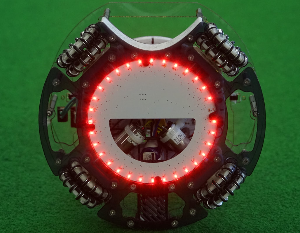
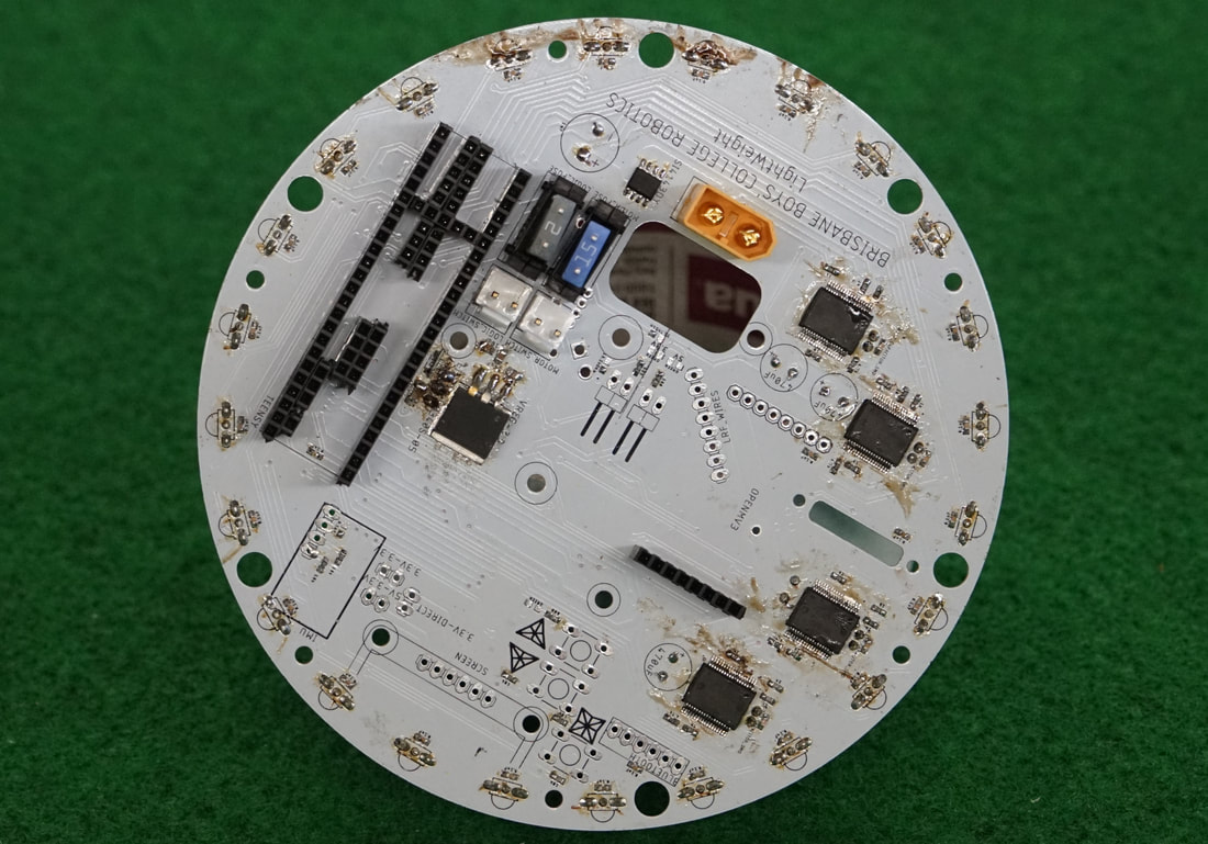
The robots’ electrical system is a combination of 3 printed circuit boards (PCB’s). PCBs were used in this robot to reduce the number of external connections, increasing the reliability of connection to different components. The PCBs are connected to each other by Flat Flex Connectors (FFCs) like ones used in many smartphones and tablets in the Tech-Industry. The PCB on the Bottom Plate (Light Sensor PCB) is used to detect the white line. The PCB on the Middle Plate (Main PCB) holds all the main circuitry and the bulk of the components. It holds the two micro-controllers which calculates the robot’s movement.
|
|
|
The light sensor PCB holds:
|
The Main PCB consists of:
|
Laser range finders
|
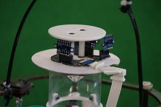
The PCB above the cone is the LRF (Laser Range Finder) PCB. This PCB holds four Laser Range Finders which can detect the robot’s distance from the walls. There are mounted at the top of the robot so it can see over other robots. This array of 4 sensors allow the robot to have accurate positioning on the super team field and enhanced vision in regular game play.
|
|
360 camera
|
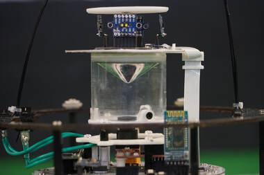
The 360-degree camera vision system is comprised of the Open MV H7, a custom moulded mirror and acrylic tube. The mirror is shaped as a cone and is vacuum formed over an impression to create a detailed mould. The camera is positioned so that it looks vertically at the cone, then through the mirror on the cone can see the entire field. A series of brackets allow the cone to be positioned to the centre of the camera’s field of view. A circular piece of card is placed above the cone to protect the camera from glare which would wash out the image.
|
