Overview
The structural design of the robot was created in Autodesk Fusion 360, and the PCBs were designed in Autodesk EAGLE. These programs were used since the different file types were compatible with each other, making it easier to visualise a finished robot and simulate the fit of components. Custom made parts, incorporated in the design, were either Laser Cut or 3D Printed. The PCBs were made at a fabrication service.
Multi-layer design
|
Camera Cap
|
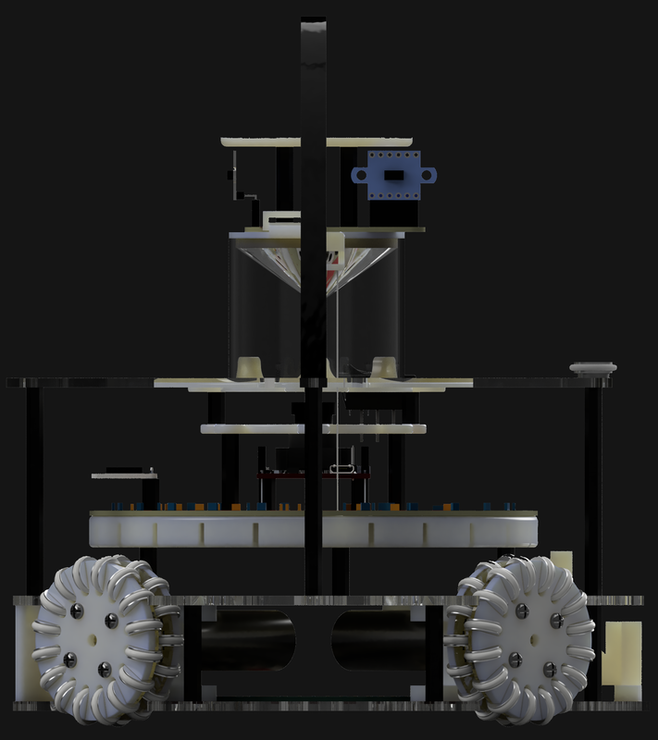
The robot is comprised of three separate layers which form the frame of the robot. This creates a robot which is easily accessible for both production, maintenance and repairs. The chassis is made up of three laser cut poly-carbonate plates. The three plates are connected by lightweight nylon standoffs.
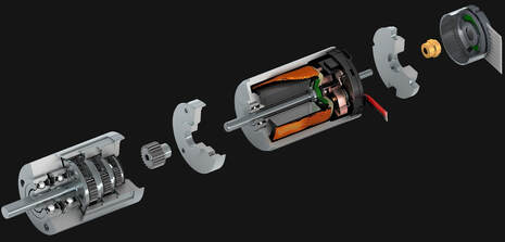
Drive System
|
|
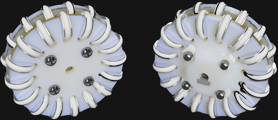
Maxon DCX 19's are used with a 16:1 gearbox. They have a custom made omni-wheel attached to them to allow the robot to move in any direction. The omni-wheels are double layered so that they increase the grip on the carpet. This is useful for avoiding the line and having better control during ball following.
Stability and ease of use
|
A combination of laser cut plates, 3D prints and fasteners create a structurally stable robot that is easy to build and repair. 3D printed components have a huge range of freedom, and by increasing the temperature of the extruder, we get stronger parts at the expense of some print quality. Laser cutting, while only being 2 dimensional, provides plates that are consistently strong and lightweight. Nylon standoffs are used as connectors between layers of the robot, as they are rigid enough to support the robot but have enough give to absorb impacts.
A magnetically attached battery door allows quick removal of the battery |
|
